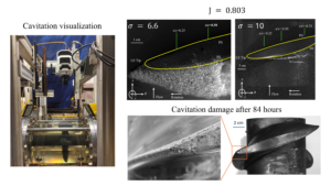
Additive manufactured ducted propeller (A6061, Tip gap: 2 mm)
Objectives:
- Visualize cavitation erosion on an AM propeller and the evolution of surface pitting over time.
Approach:
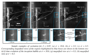
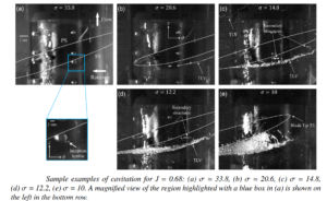
- The propeller was continually operated in the established design conditions, viz. Advance ratios J= 0.803, 0.85, 0.9 at cavitation number σ= 10.
- Imaging was done at 15 kHz to detect incipient and observe developed cavitation in the tip region.
- Phantom v2640 high-speed camera was used for the same (1024 x 976 pixels).
Results:
DUCTED PROPELLER (Acrylic, Tip gap: 2 mm)
Previous Turbomachine results
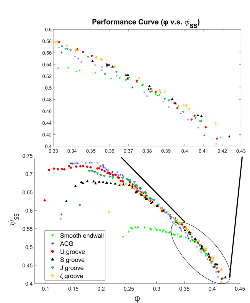
Effects of Axial Casing Grooves (ACGs) on the performance of axial compressor.
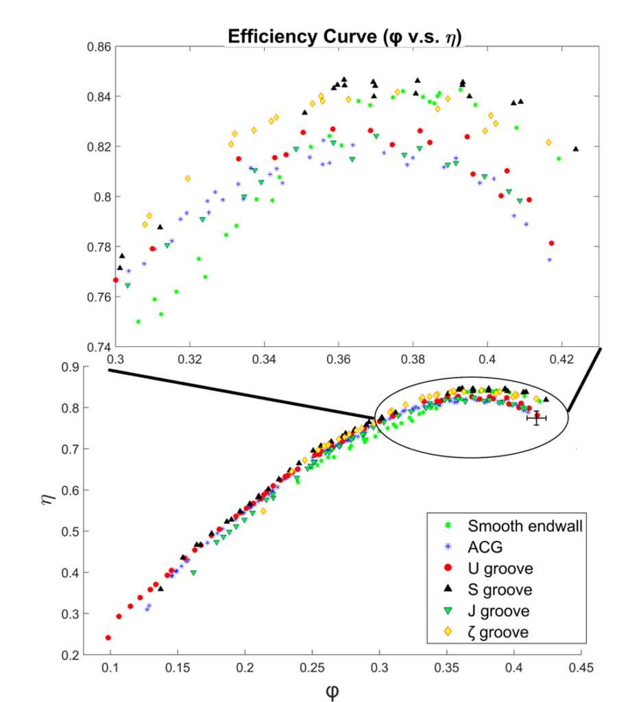
Effects of Axial Casing Grooves (ACGs) on the efficiency of axial compressor.
______________________________________________________________
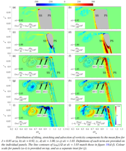
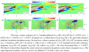
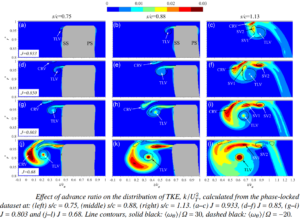
FLOW VISUALIZATION USING CAVITATION
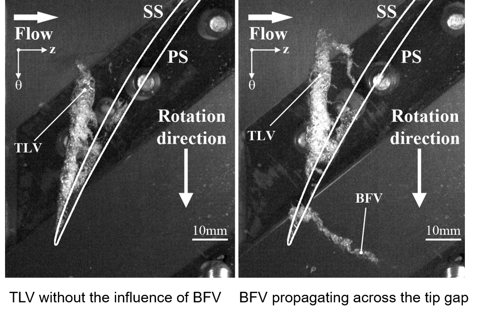
Formation of Tip Leakage Vortex (TLV) and Backflow Vortex (BFV) in axial compressor.
______________________________________________________________
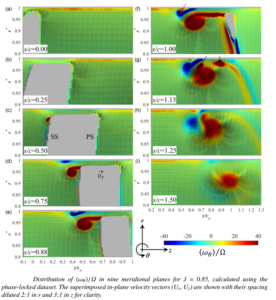
STEREOSCOPIC PARTICLE IMAGE VELOCIMETRY
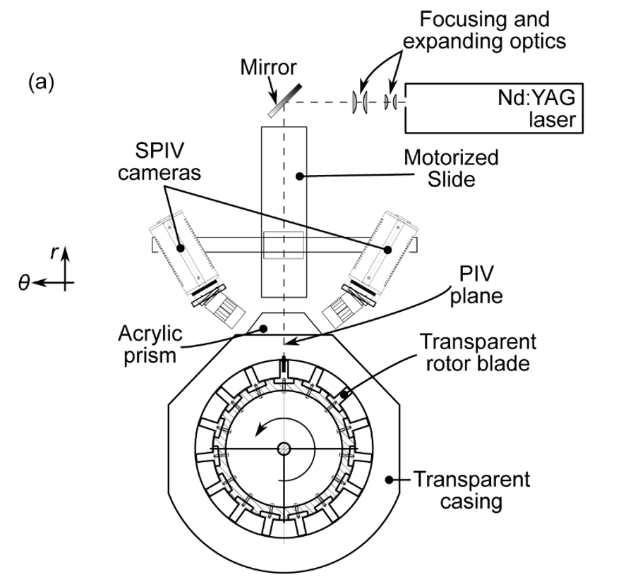
Sketch of a typical SPIV setup.
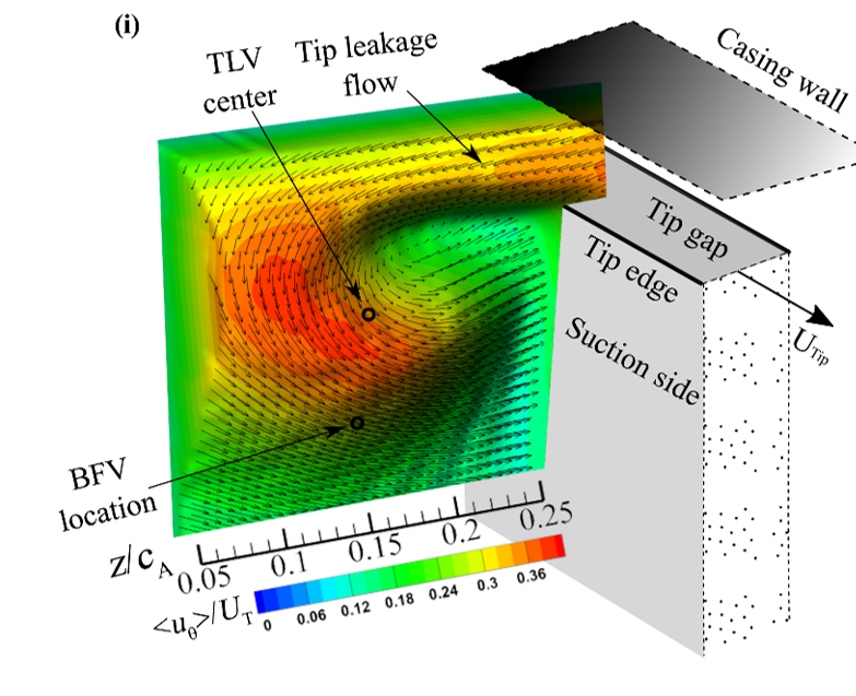
Three-dimensional structure of the TLV