People
| Previous Graduate Students | Yuanchao Li, Huang Chen |
| Graduate Student | Subhra Shankha Koley, Ayush Saraswat |
| Project Supervisor | Prof. Joseph Katz |
| Design & Technical Support | Dr. Yury Ronzhes |
Introduction
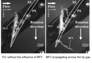
Role of BFVs at the onset of stall: Our earlier studies detailing the flow in the tip region of an axial compressor identified that the circumferential propagation of Backward Flow Vortices (BFVs), originating from the interaction between tip flow and main passage flow below the TLV center, play an important role in the onset of stall. They affect the blade loading and delay’s TLV roll-up. The size and frequency of BFV increase during stall.

Delaying Compressor Stall: Semicircular Axial Casing Grooves were used to delay the stall. It achieved a 40% reduction in flow coefficient at the onset of stall, but its peak efficiency decreases by 2.4%. Detailed Particle Image Velocimetry measurements in the tip region show that the semicircular ACGs:
- Entrains parts of TLV which cut off the generation and circumferential propagation of BFVs.
- The outflow from the grooves causes periodic changes to the incidence angle.
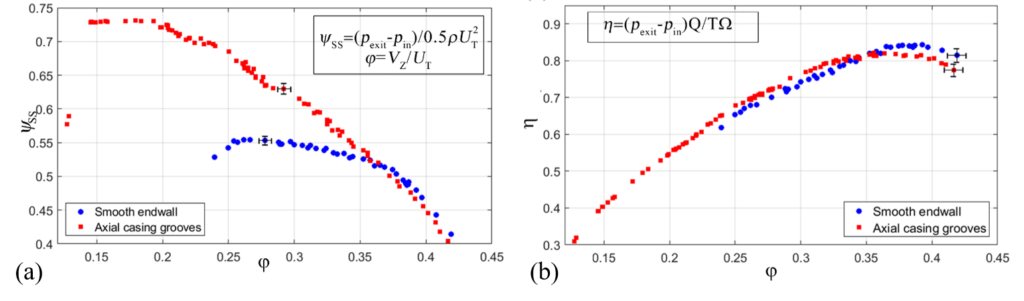
(a) Static pressure rise across the compressor, (b) efficiency of the compressor
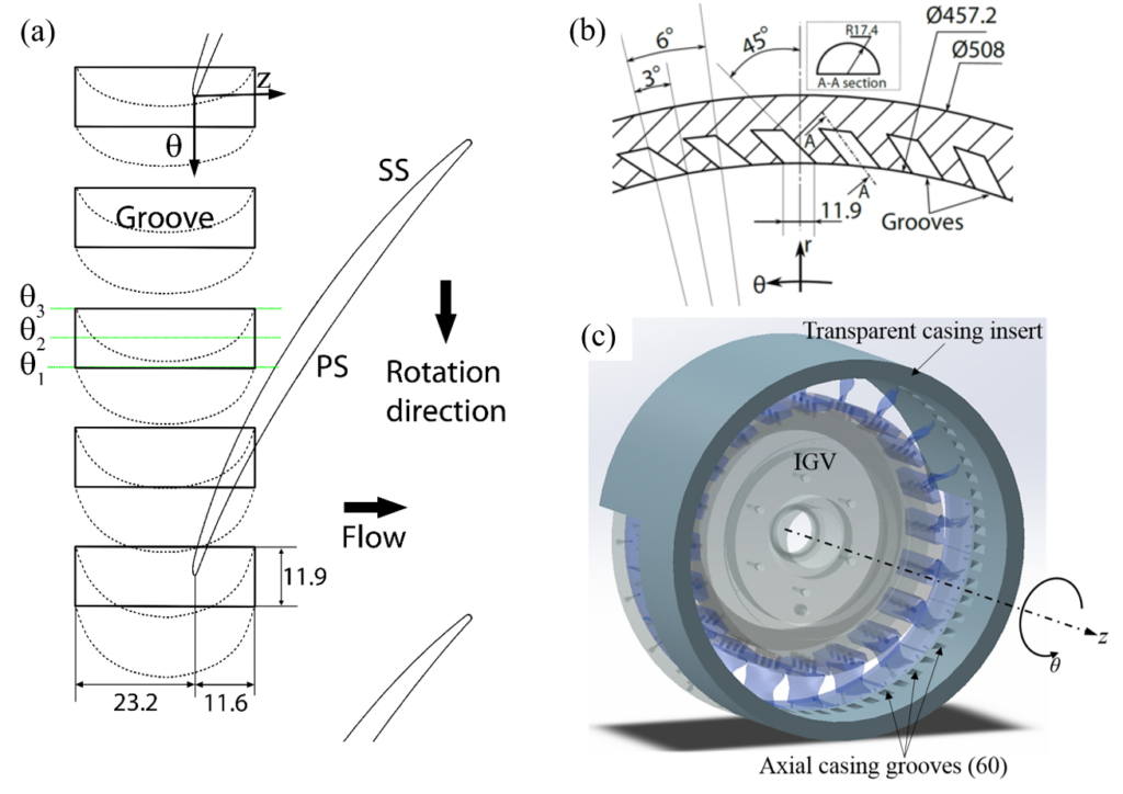
Geometries of the axial casing grooves: (a) a radial view, (b) streamwise view (looking upstream) and (c) perspective view
Groove Shape Optimization: Investigate the effect of different groove geometry with flow entering the groove at a similar orientation but exiting at different directions. This would decouple the effect of periodic modulation of incidence angle from the TLV ingestion.
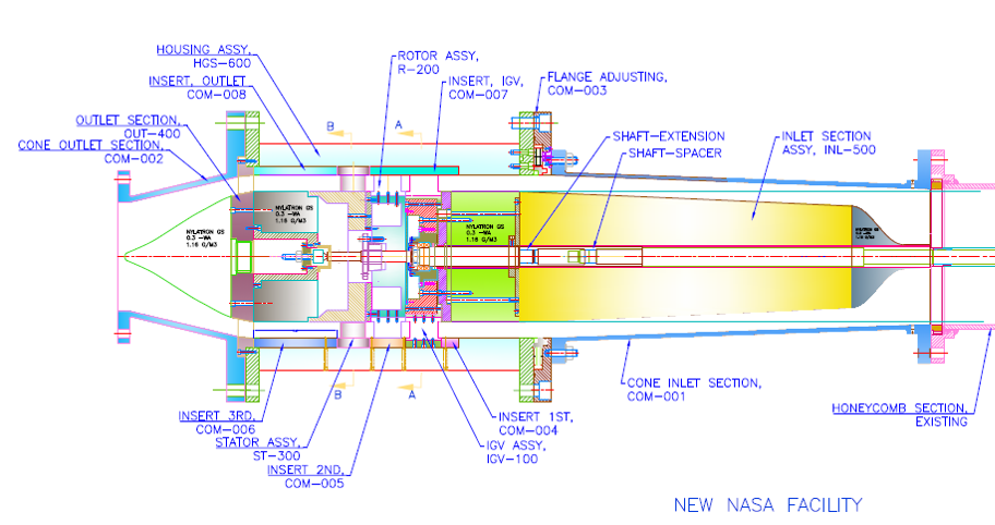
Facility
We have used the same NASA compressor to test the grooves. More details about the facility can be found in the tab under the heading of NASA compressor.

Horizontal water tunnel
The NASA Compressor
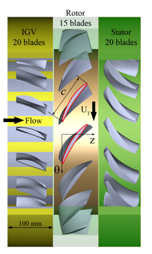
Configurations of the Compressor.
Groove Geometries
- The circumferential distribution of grooves was similar in each of the different geometry.
- The inlet to each groove was the same. The outlet was directed along/against the IGVwake/rotor motion.
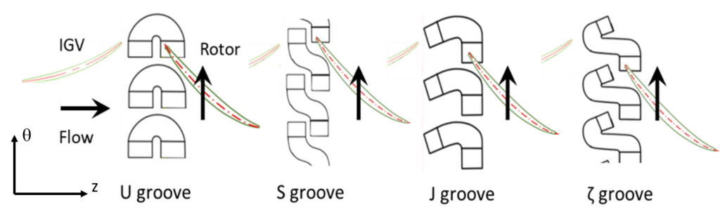
The different groove geometries.
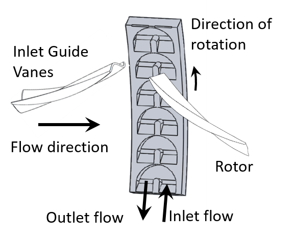
Detailed illustration of the groove with rotor and IGV
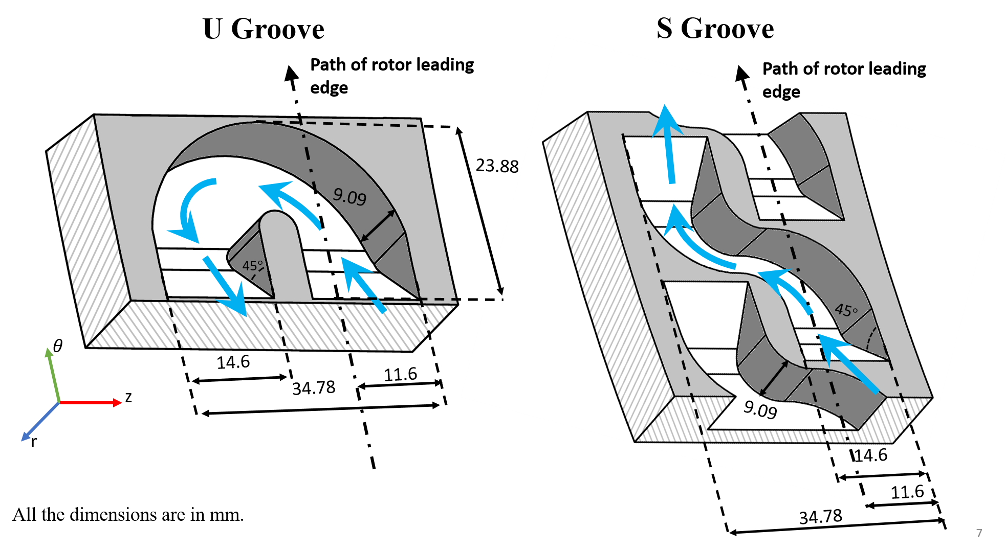
Detailed 3D geometry of U and S grooves.
Experimental Setup
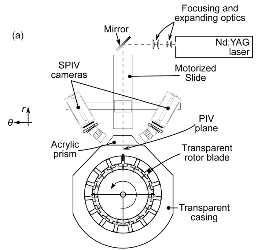
Schematic of the Stereo-PIV setup
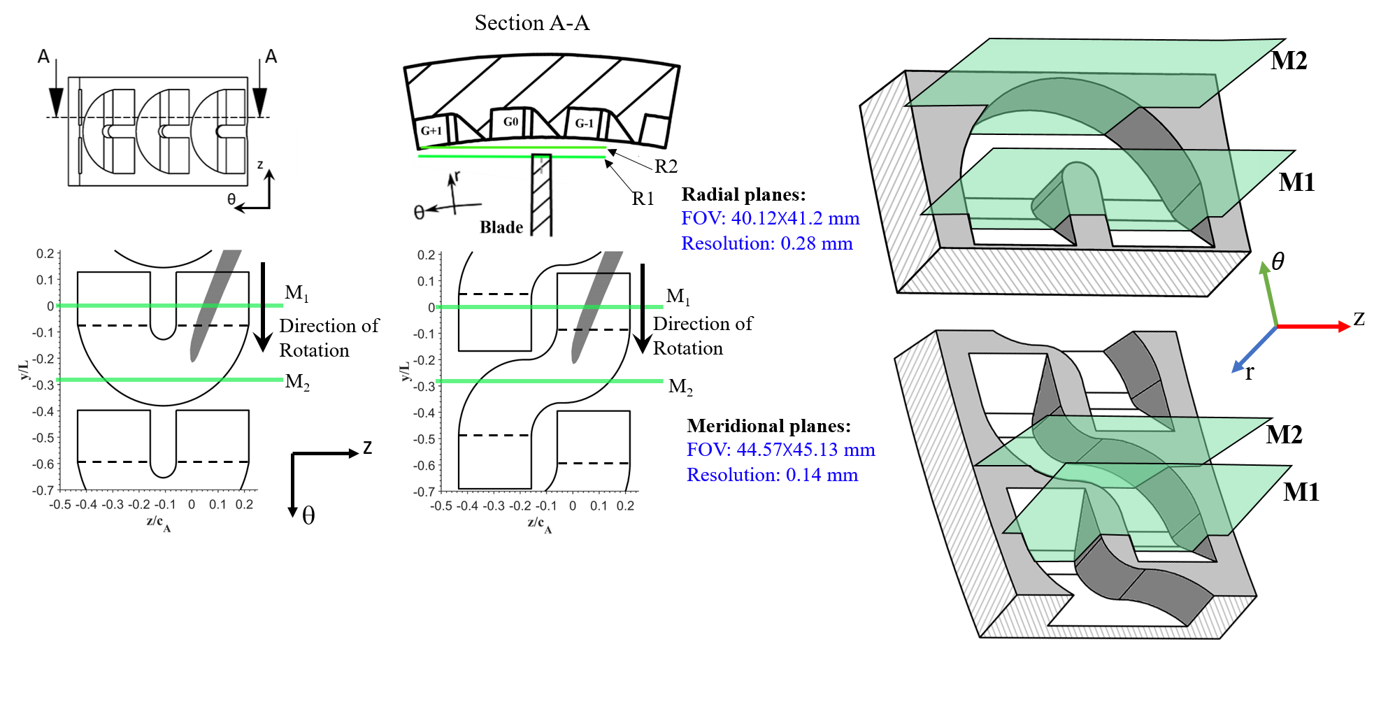
Sketches of Stereo-PIV planes.
Results
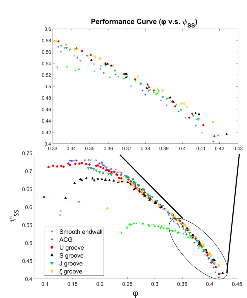
Performance curve showing the different stall flowrate for different grooves. U grooves are most effective in delaying stall. S grooves have a milder improvement in stall suppression.
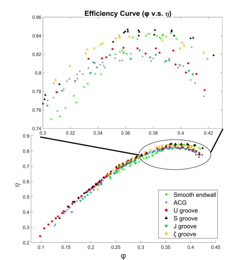
Efficiency curve for all the grooves. S grooves maintain the efficiency of untreated endwall while having a milder reduction in stall flowrate. U groove, J groove, and semicircular ACG have a peak efficiency loss compared to smooth endwall.
Groove-passage flow interaction trends for U and S grooves at the pre-stall flowrate of untreated endwall (\phi =0.25) in the Radial R2 plane.
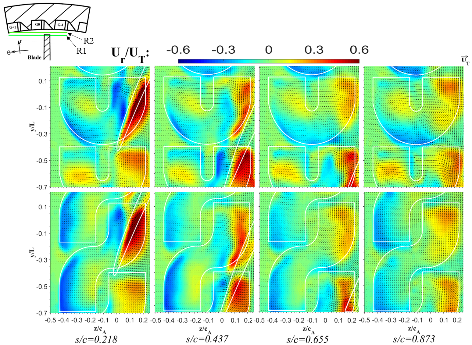
Ensemble-averaged in-plane velocity vectors ( Uz, Uθ) superimposed on color contours of the radial velocity component in R2 plane at flowrate = 0.25. The values of s/c indicate the intersection of the M1 plane with the blade chord.
- Inflow into the groove peaks when it is aligned with the PS of the blade, but persists even when the blade clears the groove.
- The outflow from the U groove is centered near its base (not expected).
- Outflow from the S groove is aligned along its upstream end (as expected).
Publications
With link to publication See example below:
van Hout, R., Katz, J., (2004) A method for measuring the density of irregularly shaped biological aerosols such as pollen. Journal of Aerosol Science. 35(11) 1369-1384.