The actual simulation on the layout will be performed on the Extracted cell view of the inverter. This cell view contains all the information necessary for Spice Simulation.
In the Library Manager, double click on the Extracted cell view of the inv. A new editing window with the analog extracted version of your inverter should appear.
Left click Editing:Tools->Analog Environment. The analog Artist window will appear. We will perform a transient analysis on the layout of the inverter and the steps are very similar to the ones we described earlier.
Left click Analysis->Choose. Specify a transient analyses to 10n
Left click Outputs->To be plotted->Select on schematic. Now click on the poly pin of the input pin and on the metal pin of the output pin. The poly and metal layer will change color, indicating that they are selected for plotting the results.
Go back in your Analog Environment window. Now we need to specify how the pins of the layout are connected. We need to specify that the vdd and vss pins are connected to 5 volts and ground respectively. Also we need to specify an input pulse source to the in pin. We are going to specify this with the graphical stimulus editor.
Left click Analog Environment:Setup->Stimulus->Edit Analog. In the new window click graphical to begin editing the stimulus.
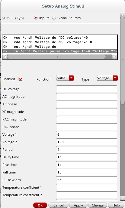
First connect vdd and gnd to the appropriate voltages. Select vdd, check enabled, make sure function is dc and type in 1.8 under DC voltage and hit the change button. Do the same for gnd but with 0.
Now connect the input to a voltage pulse by selecting and enabling it. Change the function to pulse. Put 0 for Voltage 1 and 1.8 for voltage 2. Refer to the picture below for the detailed transient simulation settings.
Hit okay and run the simulation now by clicking on Simulate->Run. You should observe similar results to the ones you obtained from the transient analysis on the schematic.